Calibration interrupts production with significant downtime. The transfer of parts to separate measurement instruments also adds to production time.
Increasingly, a coordinate measurement machine (CMM) is used to inspect complex features, often acting as a bottleneck, which further slows production. On-machine measurement can remove this bottleneck and drastically reduce the time required to measure parts.
A lack of confidence in machines inspecting their own work has, however, prevented widespread adoption of on-machine measurement. Now, rapid machine verification methods make traceable on-machine measurement possible, enabling an increase in production speed while improving quality.
Probe replaces cutting tool
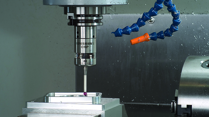
On-machine measurement means inspection on a machine tool, immediately after the machine has finished cutting metal. An automatic tool changer is used to remove the cutting tool from the spindle and replace it with a measurement probe. The machine then controls its axes just as it would when cutting metal, but instead it is manoeuvring the measurement probe to make contact with critical features of the part. When the probe makes contact, encoders in each axis of the machine tool record the coordinates, enabling coordinate measurements to be made using the same principles as a CMM.
Carrying out measurements directly on the machine tool has a number of benefits. It saves time by removing the need to remove and refixture parts before they can be measured. It prevents the CMM from becoming a bottleneck that limits production rate. It also enables issues to be detected closer to the point of failure, enabling better quality improvement.

A Renishaw on-machine probe
The problem with on-machine measurement is that defects in the part caused by kinematic errors in the machine tool are unlikely to be detected. For example, the linear encoder in the X-axis might have a scale error that means all features are elongated by 0.2% in the X-axis. The same linear encoder would be used to measure these features and they would therefore appear to be the correct length.
The same principle would apply to any other kinematic error, such as a machine being knocked out of squareness or slideway wear causing straightness errors.
One simple way to work around this is to get machines to check each other’s work. It is much less likely that two machines will simultaneously develop the same kinematic errors as each other. Therefore, if work is swapped between two similar machines, the above problems can be reduced.
Although this loses some of the benefit of measuring without refixturing, if pallet loading systems are used this will be minimised. Ideally, however, a machine should be able to reliably check its own work. This requires a way of bringing metrological traceability into on-machine measurement.
Machine-tool traceability
Metrological traceability means that a measurement system has an unbroken chain of calibrations connecting it to the fundamental standards of measurement. In the case of a machine tool, this means the SI definition of the metre. Each calibration must consider all sources of uncertainty, so that the increasing uncertainty that accumulates as each calibration takes it further from the fundamental standard can be properly accounted for.
If a machine has been recently calibrated, then measurements it performs have a degree of traceability. A risk remains that a fault of some kind has introduced an error which will mirror itself in a part defect and error of measurement, therefore meaning the part defect will not be detected.
If the machine could be recalibrated after part measurement that would give increased confidence, but this would normally be totally impractical. Traditional machine-tool calibration requires significant downtime and is a highly skilled job. Until recently, machine tools were carefully calibrated by the manufacturer and they would only be recalibrated if errors were observed in the parts they produced.
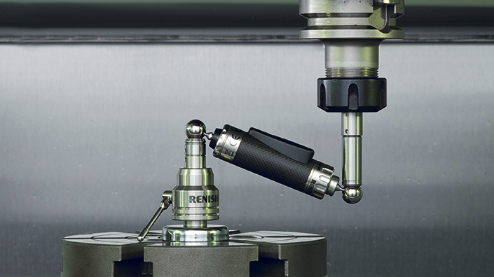
In the quest for improved quality and zero defects, many manufacturers now perform regular checks and recalibrations. The ball-bar enables general health checks to be completed in 20 minutes, while multi-line laser systems can greatly reduce the time required for a full calibration.

A Renishaw ball-bar
I recently wrote about how the Etalon Multiline integrates lasers into machines so they can be fully self-calibrating (Industry Pulse, Professional Engineering No 2, 2019). In theory, this will enable a full calibration to be carried out in minutes with no human intervention. In practice, such an approach is only suitable for large machines and is very expensive.
“Systems such as Renishaw’s XM-60 multi-axis laser enable a machine’s errors in all six degrees of freedom to be quickly measured, giving a true understanding of the machine’s performance,” says Tom Ellis of Renishaw.
Rapid machine-tool verification
New rapid machine-tool verification methods can be performed automatically in just a few minutes, to verify that the machine is operating within tolerance before removing metal from high-value components. These techniques use the on-machine measurement probes that are already present on the machine, combined with relatively low-cost artefacts. Probing these artefacts in a number of locations is a simple way to verify that nothing has changed since the machine was last calibrated.
The artefacts do not need an independent calibration. They are simply measured immediately after the machine tool is calibrated, providing baseline measurements that are stored in the machine tool’s controller as a set of variables.
Rapid verification using artefact probing involves three stages:
1. Baseline probing is performed a short time after the machine has been calibrated, when it is known that the kinematic errors are well within tolerance. The artefact and probing routine are exactly the same as will be used in stage two. The coordinates of the probe surfaces from the artefact are stored on the machine-tool controller as R-variables.
2. Probe artefact before cutting to verify that kinematic errors are within tolerance and provide traceability for subsequent probing operations. Probed surface location and direction ensures sensitivity to all the kinematic errors of the machine tool with sufficient spatial range and resolution. The actual design of artefact and consideration of probe positions depends on the size and configuration of the machine tool.
3. Probe cut surfaces to fully verify machine-tool accuracy. These surfaces may be roughing cuts or specially made sacrificial cuts. As with the probed points, they must cover the range of positions and directions so that the machine is properly verified. It may also be important to include representative features such as interpolated radii to verify the performance of the machine under circumstances where dynamic and controller errors may become significant.
Artefact probing
Artefact probing is ideal for rapid machine-tool verification. It isn’t a full calibration that would independently quantify each error source to enable compensation. Instead, the verification tests are designed to be sensitive to all error sources, without being able to separate them. When a problem has been detected, a calibration is then required. Most CNC machine tools are now supplied with a measurement probe and an automatic tool changer.
Probing a pre-calibrated artefact can verify that kinematic error parameters are within tolerance and provide traceability to any subsequent probing operations. Subsequent probing of roughing cuts, or sacrificial cuts made for testing purposes, can then verify the complete dynamic performance of the machine tool with sensitivity to all error sources including spindle errors, tool wear and controller errors.
Content published by Professional Engineering does not necessarily represent the views of the Institution of Mechanical Engineers.